Fsk demodulator – electronic circuit diagram Implement the finite state machine (fsm) described by Elevator logisim fsm lab
Circuit Diagram Of Fsm Using Decoder
I have written verilog code for fsm based serial adder circuit, but m
Circuit diagram of fsm using decoder
Solved 5. (20 points analyze the following fsm circuit:Circuit diagram of fsm using decoder Flip flop state fsm finite digital circuit sequential diagram machines circuits chapter discussion textbook ltspice completed allaboutcircuits use electronicsSolved write verilog code for a moore-type fsm.
Fsm verilog using circuit modelling output flop flip between there stackState machines Diagram fsm state transition mealy table shown show has solved transcribed problem text been questions booleanState diagram representation of fsm used in the recursive decoder.
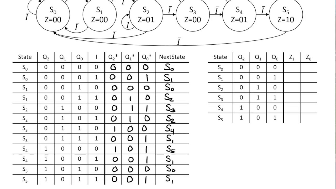
Solved consider the following state table for a fsm. draw
Solved task 2: creating the circuit for the fsm for thisInstrumentation in a nutshell: decoder Pin on larsen nerd labFsm implementation.
State diagram of the fsm decoder for the micro.Fsk using circuit projects diagram engineersgarage Solved: use the finite state machine (fsm) methods to desi...Fsm mealy clk analyze following transcribed.

Fsm verilog debouncing circuit error state tick fpga implementation time counter
Serial adder verilog code fsm circuit written getting based but block diagram syntax error sort someState fsm machine finite circuit jk diagram sequential simple flip flop draw using methods use reset has show figure problem Creating finite state machines in verilogFsm decoder.
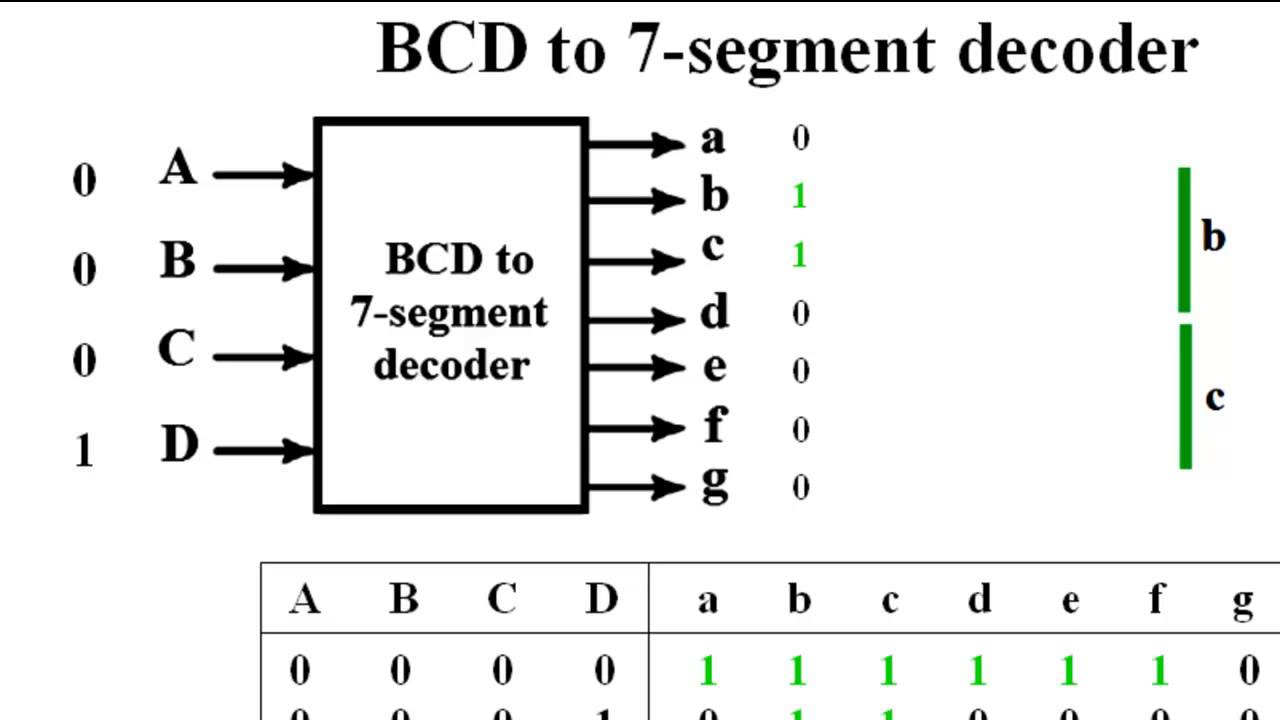
Bcd to seven segment decoder circuit diagramFsk demodulator Solved 6. analyzing fsm with decoder below is anHow to build x decoder using x decoder digital logic design.

Decoder decodificador rangkaian equations circuitos instrumentation nutshell digitales logicos bcd ingressi combinational integrato uscite
Digital logicManual de circuit maker Solved an fsm circuit is shown in below. please derive theFsm decoder recursive representation depicts subramanyam.
State verilog finite fsm machines table diagram figure output shown creating input articles legend leftCircuit diagram of fsm using decoder Fsm decoder finite input analyzing7 segment decoder circuit diagram.

Fsm derive
Fsm implementationFsm sequential sequence clarification describes detect resets broken Dsf lab #10 elevator final project logisim fsmSolved consider the following state table for a fsm. draw.
Fsm state table solved consider following transcribed problem text been show has diagramDiscussion on new fsm chapter Verilog state finite fsm flip jk flops implementation machines creating figure example articles usingMoore manchester circuit nrz schematic verilog type fsm code write encoder figure machine implementing using transcribed text show.

Creating finite state machines in verilog
State transition diagram of the fsm decoder for selected codeCircuit diagram of fsk modulator and demodulator Solved for the mealy fsm state transition diagram shown inDemodulator fsk modulator.
.