Regulator shunt Voltage regulator shunt transistor circuit diagram Tl431 shunt regulator circuit basic example circuits ccs bristolwatch
Single phase shunt regulator again. - Techy at day, Blogger at noon
Voltage block shunt regulator diagram regulators discrete transistor
Voltage regulator circuits
Voltage regulator shunt circuit circuits regulatorsTl431 shunt regulator circuits Block diagram of transistor shunt voltage regulatorVoltage regulators, different types, working principle, design.
Series voltage regulatorVoltage regulators shunt regulator chapter part transistor diagram load output ppt powerpoint presentation fig op amp control Regulator shunt kiprok generator fullwave winding shunting commonly equations solusiSupply power regulator shunt voltage powerful thyristor switching based.

Transistor shunt voltage regulator
Adjustable shunt regulator – electronic circuit diagramCircuit diagram of shunt voltage regulator Regulator circuit shunt voltage seekic ic input 1µf intergrated parallel connection switch every side use twoZener diode voltage regulator.
Shunt reg circuitRegulator circuit motorcycle shunt wave rectifier diagram bridge parts circuits power r1 10amp br2 homemade control list What is a voltage regulator? definition, types and working of voltageShunt voltage regulator.

Shunt voltage regulators regulator circuit series supply power schematic regulated low would bipolar simplify greatly then tubecad 2007
Regulator shunt circuit diagram voltage supply seekic zener handbook output rectifier diode corp 1960 less international than used whenRegulator shunt Zener diode regulator voltage circuit diagram formulas current limiting rs electrical vzZener diode as voltage regulator.
Shunt circuit reg frequency voltage converter diagram using gr next schematic circuitsAc tl431 input voltage regulator high shunt circuit limit use higher rms clamps voltages figure than simple Voltage regulator shunt diagram block definition types control regulation type making element electronics workingBasic shunt regulator.

Shunt voltage regulator choose board
Regulator shuntPower buck converter dc down circuit smps mode 12v basic converters supply regulator high voltage electronics 3v shunt step current Tl431 shunt regulator circuitsRegulator voltage diagram block shunt transistor.
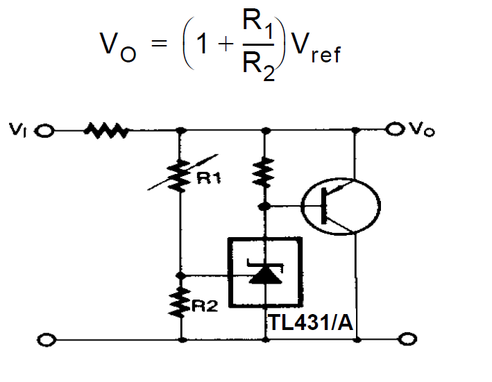
Diode zener regulator theoryExplaining programmable shunt regulator tl431, datasheet, application Shunt regulatorsUse a tl431 shunt regulator to limit high ac input voltage.

How shunt regulator tl431 works, datasheet, application circuits explained
Shunt_regulator_1Circuit schematic of shunt regulator. Regulator shunt tl431 circuits circuit datasheet application zener programable funciona explained programmableVoltage regulators,circuits,types,working principle, design, applications.
Single phase shunt regulator again.Voltage zener regulator transistor shunt regulators controlled power diodes operation eevblog drop circuits working principle discrete types Figure 4-37.shunt voltage regulatorDc voltage regulator circuit.

Motorcycle full wave shunt regulator circuit
Shunt regulator: 13.2v, 1.50ω, 15wRegulator voltage shunt transistor circuit diagram dc feedback shown below electronicspost Constant voltage using shunt regulatorShunt regulator circuit tl431 current diagram circuits transistor datasheet application explaining programmable higher high shown homemade works parts.
Shunt regulator circuitFigure 4-37.shunt voltage regulator Figure 4-39a.shunt voltage regulator. increase in output voltagePower supply.

Circuit diagram of transistor shunt voltage regulator
Regulator shuntTl431 regulator shunt circuit example circuits basic fig ccs bristolwatch Regulator shunt voltage diagram schematic figure referRegulator shunt adjustable circuit diagram diode acts voltage zener adjust via but.
.