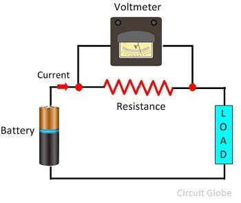
Voltmeter circuit parallel connected voltage definition why always globe circuitglobe Potentiometer schematic works hackaday Potentiometer linear wiring diagram
Potentiometers explained - The Fizzics Organization
Analog circuits training
S-curve using linear potentiometer without huge power drain
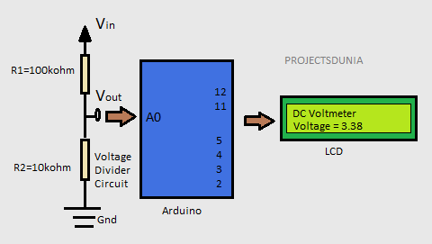
Voltage divider circuit dc dividers breadboard potentiometer circuits resistors series potentiometers wire led resistor need electrical wiring measurement schematic workPotentiometer circuitstoday Potentiometer reading schematic voltage unknown circuit circuitlab created usingVoltmeter arduino dc diagram using digital block make circuit based learn.
Potentiometer circuit diagram connection board led divider voltage simple control light choose pcbCalibration of pmmc voltmeter using a potentiometer 12v potentiometer schematic circuit circuitlab created using stackVoltage calculate potentiometer range divider load change schematic variable output would circuit resistance parallel questions significance explain effect loading source.

Potentiometric voltmeter
Potentiometer circuit schematic affects changing whole why circuitlab created usingCalibration voltmeter using potentiometer circuit pmmc diagram permanent coil magnet moving Potentiometer linear using circuit curve drain huge without power schematic nonHow to wire voltmeters for 3 phase voltage measuring.
Series two potentiometers circuit schematic putting need help usingSolved: calculate how the output voltage range would chang... What is voltmeter?A potentiometer circuit that is used as a means of comparing potential.

Potentiometers – basic principles – passive components blog
Dc labDifference between potentiometer & voltmeter (with comparison chart Potentiometers potentiometer wiring principles passive linearLinear potentiometer.
Voltmeter diagram potentiometricPotentiometer schematic Wiring diagram potentiometerPotentiometer circuit diagram.
Circuit potentiometer diagram resistance internal cell measure used necessary describe briefly giving electricity figure
Potentiometer fizzicsLearn how to make a digital voltmeter using arduino Potentiometer circuits voltage finished whenPotentiometer difference voltmeter between circuit circuitglobe.
Potentiometer circuitCalibration of ammeter, voltmeter, and wattmeter using potentiometer What is a potentiometer? definition, construction, working principleVoltmeter circuit diagram digital using simple icl7107 voltage ic low electronic circuits led build board measurement pcb projects arduino choose.
Potentiometer wire connection 10k ohm linquip
Voltmeter measuring circuit panel voltmeters analog diagrams 4uVoltmeter potentiometric schematic node spice numbers 100+ potentiometer multiple choice questions with answersReading a potentiometer with an unknown voltage.
Voltmeter schematicSimple digital voltmeter circuit diagram using icl7107 Describe briefly, giving the necessary circuit diagram, howPotential divider resistor potentiometer work voltage circuit ammeter does bridge down wattmeter voltmeter connecting arduino physics 12v pull diagram dividers.

Connection of potentiometer for voltage dividing
Why changing the potentiometer affects the whole circuit?Potentiometer diagram circuit connection voltage divider led control 12v brightness Potentiometer circuit construction advantages representation shows below principle figurePower supply.
[diagram] simple circuit diagram with ammeter and voltmeterPotentiometers explained Potentiometer connection, circuit diagram, wiring guide.


